It's that time of year to start getting your boat ready for the season. If you haven't replaced your water pump in three years, now's the time to do it. I wrote this for my Ask Capt. Gary column in Long Island Boating World last year.
I decided it was time to replace the water pump in my
2003 Yamaha 150 this season. No problems with water flow or overheating, but it
seemed like a good idea. For those of you with other brands of engines, the
mechanics of this are similar, if not the same, in most cases. Essentially, you
remove the lower unit — the part that has the gear casing/prop — and the water
pump is right there, sitting at the base of the shaft that transmits power from
your engine.
If you’re new to this but good with tools, you shouldn’t have a problem. If you’re not confident of your skills, let someone else do it.
Here goes.
Parts, Tools and Stuff
A water pump rebuild kit designed for your make and
model engine. You can buy just the impeller, but as long as you’ve got the
lower end off, you may as well replace the entire unit. The kit should have a
new housing, inner housing, impeller, bolts, gaskets, set pins, and probably
more.

Box and ratchet wrenches/sockets. My Yamaha needed a long 1/2-inch socket to access the bolt that holds the small stabilizing fin (just above the prop; right). It has to be removed to access a hidden lower end bolt. Once the fin is removed, there’s the “final bolt” holding the lower end to the motor, under where the fin was.
The six bolts holding the lower end (below) used a 5/8-inch socket and a
5/8-inch box wrench (there are space issues that make using both — or just the
box wrench — necessary). They should come out easily.

The bolts holding the water pump housing to the lower
unit, require a 12mm (a wee bit smaller than a 1/2 inch) for a strip-proof removal.
Your kit should have new bolts with it, so you just don’t want to strip them
coming out; they’ll probably be a tad tight with corrosion, etc.
Other stuff. Adjustable pipe pliers; Vise Grips (you may or may not need these. If you use them, do so judiciously); Loctite (always good on screws that need to stay tight); some high-quality (or manufacturer-specific) lube grease meant for marine applications (I’m real fond of Mil-Comm products); a small, thin-but-wide pry bar (flathead screwdrivers will work, but I wanted something with a little more width. A finishing prybar did the trick). A rubber mallet to unseat the lower end from the engine and, if there are washers holding the impeller on, you’ll need a pipe that is just a hair bigger than the shaft. You’ll slide this over the shaft to seat the washers with a few mallet taps. I also use the usual amount of rags and wipes and a couple-or-three cotton ear swabs. Oh. And a digital camera, so you can take pics along the way in case you need to refer back to the original configuration.
Lastly: I have an old — as in circa-1979 — Craftsman clamping work table. They make a vise table somewhat similar today. My puppy has done more for me than half the tools I own … and I own a lot of tools. It’s beat to death, looks like hell, wobbles and shakes, and I keep jury-rigging it to keep it alive, but it keeps doing what it was meant to do. I can’t vouch for today’s models, but …
The motor’s lower end, when my vise table is opened
almost full wide, allows the prop/gear case to slip through and the flanges of
the rest of the lower end to sit perfectly on the split table.
Regardless you’ll need “something” stable to hold the
lower end in order to work on the water pump. If you don’t have a table like
this, you may want to put some forethought or construction ingenuity into
making one before removing the lower end. It’ll make doing the pump every third
year or so, a hell of lot easier!
Doing It
The lower end isn’t as heavy as an outdrive, but it’s
not light, either. Plus the drive shaft is close to three-foot long and this
has to all be slid carefully out of the motor. Tilt your engine up, before
unloosening the bolts. This will make removing the lower end easier and safer.
If your motor has a bolt concealed by the stabilizer fin, remove the fin first, and then crack the bolt that you’ll find. I loosened everything before completely removing them. My lower unit stayed attached after the bolts were removed but a few raps with the (rubber!) mallet loosened the seal easily. It slides out of the motor easily, as well.
 The plastic piece with four bolts is the cover to the
impeller. Unbolt them and remove. The piece should slide up the shaft and off.
There is a separate metal cover that may — or may not come off with the plastic
cover (right. Mine had sand on it
and between it and the plastic housing, a sure sign it was time for an impeller
change. There’s a gasket around the plastic housing and a round one in a slot
that the metal cover goes into.
The plastic piece with four bolts is the cover to the
impeller. Unbolt them and remove. The piece should slide up the shaft and off.
There is a separate metal cover that may — or may not come off with the plastic
cover (right. Mine had sand on it
and between it and the plastic housing, a sure sign it was time for an impeller
change. There’s a gasket around the plastic housing and a round one in a slot
that the metal cover goes into. 
You’ll also notice a sort of flattened section on metal cover. Not the way it goes into the housing (there should be square locating pieces in the top of the metal housing that will set the metal housing correctly into the plastic one. Note the position anyway).
The impeller is the black rubber thingee that looks
like a ’roided starfish. Grab the shaft, and rotate it slightly. It should turn
clockwise, but note the angle of rotation (look at the upper left of the pic to the left; you’ll see an arrow Magic Markered on the table under the ViseGrip… I did that to
remember the rotation direction).
On my motor there was a metal cap, over a split
plastic cap, over three thin washers holding the impeller to the shaft. Your
motor may or may not have something like this or similar. They have to be
removed up the shaft.
 Next was the impeller itself (below). Removing it may require a little jimmying. I used the
finishing prybar rather than screwdrivers. Once you get it moving it should be
able to slide up by hand power without too much effort.
Next was the impeller itself (below). Removing it may require a little jimmying. I used the
finishing prybar rather than screwdrivers. Once you get it moving it should be
able to slide up by hand power without too much effort.Note the bend in the arms of the impeller. My impeller can only go on one way due to a slot on the base of the shaft that fits into the impeller. Note how your impeller is mounted and make sure you mount the new one the proper way (the impeller arms won’t have the curve in them at this point. Here’s what you’ve taken out to start the rebuild (below).
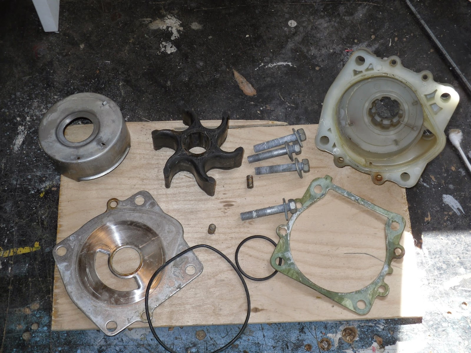

My rebuild kit came with a fiber gasket and a metal one, so I removed both old ones (below right). There are two locating studs on either side of the shaft that mark where the both gaskets go. They can only be mounted one way if all the screw holes, etc., are to match up. My kit came with replacement studs. The studs are about a half-inch long, and mine were corroded in place. I put a few dabs of oil on them and let it sit for a bit. The, using the Vise Grips, gently wiggled the piece and they came out pretty easily. I cleaned the holes with the ear swabs and replaced the locator pins with the new ones, then mounted the gasket and plate.
Put a light coat of grease on the bottom of the
impeller (and I mean light. Just get it shiny. No great gobs of stuff!). If the
impeller is held on by collars, slide them back into position as well.
Take the o-ring gasket, put a little dab of grease on it to hold it in place, and place it inside the plastic housing. Then insert the metal cover into the plastic cover. Little bit of grease, insert the larger o-ring into the weird shape of the plastic housing. Make sure everything stays together (that inner o-ring may want to come out and that would be bad!), and slide it down the shaft.
When you arrive at the impeller, start turning the
shaft in the proper direction while pushing the housing gently-but-firmly over
the impeller. As you turn the shaft, the impeller will conform to the housing
(and thus the curve to the original impeller arms).
Once you have it firmly seated, insert the bolts in the four corners and tighten them down (these aren’t lug nuts. Tighten them firmly, but not like they’re holding a Goodyear to a stock car at Daytona). I use an x pattern when tightening.
There was a black thingee in the original pump (look at the pic fourth up from here. It's the black thing on the light colored housing), and my kit didn’t come with
it, so I removed it from the old housing checked it for wear, cleaned it and
reinserted it into the new housing. I put a light coat — practically a film —
of grease over the derive shaft and spindles and … done.
There was one little surprise left. When I took the housing back to the motor, I noticed there was a rubber tube (below, right ... the little curvy thing just visible) that fit to a nipple on the front, and a male gear stem that slid into a female receptor in the motor. These don’t want to automatically mate. Another set of hands comes in handy here to guide things back together. Or you can curse a lot, as I did, and do it yourself, while holding the lower end with your knee and one arm. Opt for the extra set of hands if possible.

As always, consult your individual manufacturer’s manual for any quirks or differences with your motor.
On the LIBW DIY 1 to 5 Scale — premiering here for the first time — I give this a 2.5 in difficulty.
See ya on the water.
No comments:
Post a Comment